PV MODULE PERFORMANCE TEST
Analysis of the modules I-V characteristic, efficiency measurement and insulation, thermographic analysis.

DC INSULATION AND CONTINUITY TEST
Analysis and checks on the DC side of a plant. Verification of Continuity and Insulation Resistance.

COMPLETE TEST OF PHOTOVOLTAIC PLANT
Testing of an entire photovoltaic system. Measurement of global losses of the photovoltaic system.
![]()
FLUORESCENCE PV MODULE TEST
Pv module Fluorescence test on site, for cracks, EVA degradation and delamination detection.

PID POTENTIAL INDUCED DEGRADATION
PID (Potential Induced Degradation). Problem description and methods for photovoltaic modules testing.

PV MODULES ELECTRO LUMINESCENCE
Outdoor Electroluminescence on site for photovoltaic modules. Case studie and methodology.

PV PLANT DRONE THERMOGRAPHY
Execution of photovoltaic modules thermography with drone. Layout of thermal defects.

MODULES PID ONLINE CALCULATOR
Online PID Calculator. To perform an initial check for PID presence in your photovoltaic modules.
PID (POTENTIAL INDUCED DEGRADATION) ON PHOTOVOLTAIC MODULES

In the last period, there has been a confirmation from installers and managers of power loss plants and consequently of energy produced in photovoltaic systems. This phenomenon has been known in the literature since 1970 and was subsequently studied, analyzed and tested in June 2011 by the Fraunhofer Center for Silicon Photovoltaics which published the results of a test, according to which the PID is responsible for a reduction in power almost 70%.
Continua a leggere su Green Planner Magazine: Impianti fotovoltaici affetti da PID, come recuperare il ROI http://www.greenplanner.it/2015/01/14/impianti-fotovoltaici-affetti-da-pid-come-recuperare-il-roi/
Continua a leggere su Green Planner Magazine: Impianti fotovoltaici affetti da PID, come recuperare il ROI http://www.greenplanner.it/2015/01/14/impianti-fotovoltaici-affetti-da-pid-come-recuperare-il-roi/
Continua a leggere su Green Planner Magazine: Impianti fotovoltaici affetti da PID, come recuperare il ROI http://www.greenplanner.it/2015/01/14/impianti-fotovoltaici-affetti-da-pid-come-recuperare-il-roi/
This phenomenon occurs in particular in the PV module that is closest to the negative pole (Figures 1 and 2). The potential (ground voltage) of solar cells is usually between -200 V and -350 V, depending on the length of a string and the type of inverter used. The structure of the PV modules instead indicates a potential of 0 V, since it must be grounded for safety reasons.
A causa di questa tensione elettrica tra celle solari e struttura può accadere che gli elettroni si stacchino dai
materiali utilizzati nel modulo FV e fluiscano nella struttura messa a terra (figura 1). Ciò lascia una carica
(polarizzazione), che può modificare in modo negativo la curva caratteristica delle celle solari (figura 2).
Si è evidenziato che tali polarizzazioni sono per lo più reversibili. Pertanto le si distingue da effetti irreversibili,
come corrosione e normale invecchiamento.

Figure 1: if the inverter has the transformer, the PV modules always have a positive potential compared to the earth, the problem of the PID is limited or absent.

Figure 2: if the inverter is without transformer, the PV strings are no longer anchored to the ground and therefore the negative pole can also go to negative voltages with respect to the earth, giving rise to the PID effect.
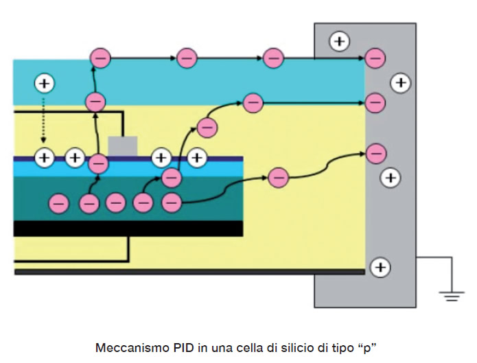
If the PV modules have a negative potential to earth, this high voltage is found between the cells of the module and the frame, which is usually connected to the ground for safety reasons. This difference in potential attracts the electrons of the materials used in the PV modules and is discharged through the frame connected to the ground. This unexpected migration of charge carriers degrades the photovoltaic effect. This generates an electron leak which disperses to the ground, generating a small leakage current. The silicon cells are weakened and the overall performance of the photovoltaic module is significantly degraded and consequently the entire production plant. This phenomenon can be observed in detail in Figure 3.

Figure 3: electron escape mechanism from the silicon cell to the ground node
The PID mainly leads to two types of degradation:
• Electrocorrosion of the TCO layer (trasparent conductiv oxide)
It occurs on the edge of the PV module and is due to leakage currents between the cells and the earth which trigger an electrochemical reaction between the moisture and sodium in the covering glass. The corrosion degrades the TCO making it lose the conductive properties and reducing more and more the efficiency of the module, this phenomenon is irreversible and has no solution if not to change the type of construction of the panels. Since 2000, the Florida Solar Energy Center (FSEC) has been researching the causes of TCO corrosion. It has been found that the modules with a-Si and CdTe cells constructed with a superstructure configuration are particularly affected. Through the use of galvanically isolated inverters and the negative grounding of the PV generator with the appropriate set, an electric field is created in which the positively charged sodium ions are repelled by the TCO layer.
• Polarization of the PV cell
In transformerless inverters, the PV field can not be grounded and is therefore floating and when the inverter is operating in the PV field, an electrical potential is created with respect to the ground, for example on a 800 V field. and you could have the negative pole of the PV field at -400v and the positive pole at + 400v with respect to earth. In the standard crystalline silicon cells subjected to "p" type doping, it is possible to generate an accumulation of positive charges on the upper side of the cell, with a consequent discharge in turn of the negative charges in the form of dispersion currents through the encapsulation material , along the frame and even passing from the front glass. In the case of silicon subjected to doping of the "n" type, negative charges accumulate on the surface and the positive ones are discharged. The phenomenon is present above all in the modules closest to the negative pole of the strings and leads to deterioration and loss of power even up to 70% in a few years.
HOW IT IS POSSIBLE TO DIAGNOSE THE PID EFFECT
There are basically two methods for identifying the PID effect. The first involves the survey of the I-V curves of the photovoltaic modules and the second the analysis in Electroluminescence (EL) of the photovoltaic modules suspected of being PID depotentiated.
• I-V curve of photovoltaic modules
It is the simplest method, but it is necessary to disassemble the module and test it with appropriate instrumentation. It provides the graphs of the trend of the current and of the open circuit and closed circuit voltage, then the value of the resistance provided by the cell (RShunt). In most cases already from the shape of the curve it is possible to have indications on the presence of PID: curve I with slow descent and VOC (maximum open circuit voltage) low indicate low RShunt, therefore presence of PID. For a more precise result, it is advisable to compare the curves measured in the field with the nominal curves supplied by the module manufacturers.

Figure 4: Survey of the I-V characteristic curve of a photovoltaic module affected by PID
Consequently, the numerical values of the test are obtained with the exact measurement of the yield drop of the photovoltaic module, as can be seen in Figure 5.

Figure 5: Result of the I-V curve measurements performed on a PV module affected by PID. Yield decreased by 26.69% after only four years of operation of the photovoltaic system.
• Elettroluminescence (EL) of photovoltaic modules
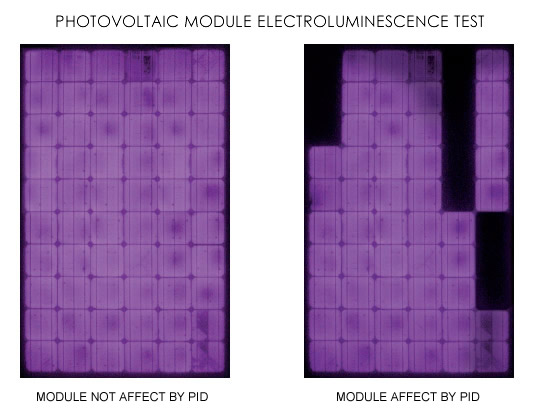
It highlights the presence of short circuits in the cells resulting in images comparable to those of the infrared test, in fact, the hottest cells will turn black, that is off, the colder white ones. This test can be done only in the absence of sunlight and does not give any indication on the level of degradation of the cells or on the percentage of power lost (to be detected by the previous method with measurement of the I-V curve). As can be seen in Figure 6, it is only possible with this method to detect the cells affected by the PID phenomenon as they have a yield that is clearly lower than the nominal yield and therefore to the healthy cells.

HOW IT IS POSSIBLE TO CONTRAST OR CANCEL THE PID EFFECT
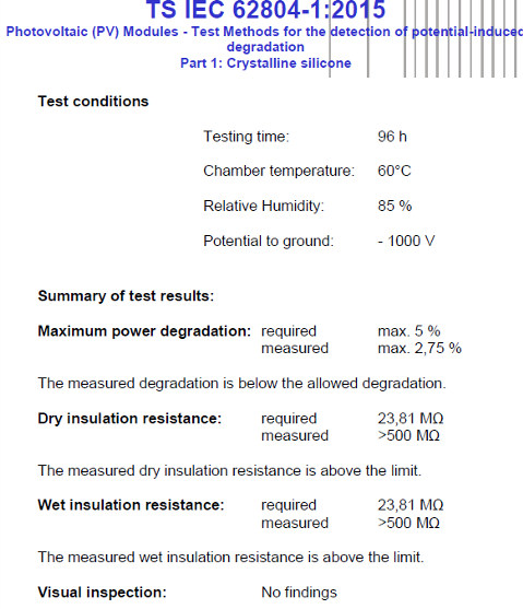
• On new photovoltaic plant: The main solution to PID is to avoid the application of a high external potential to the photovoltaic module, but obviously this is not always possible given the high voltages present in modern systems. Another solution is to adopt certified PV modules that are not subject to PID as well as adopting inverters with integrated antipid solutions (for example inverters with integrated isolation transformers). The PID FREE certification refers to the IEC 62804-1: 2015 standard and provides for destructive laboratory tests that verify the occurrence or absence of the PID phenomenon. Below is the result of a test for the real PID FREE certification of a well-known company producing photovoltaic modules:

• On plant already installed: For these systems the most economical solution is to regenerate PV modules or to subject the strings at night to a high and positive voltage with respect to the earth in order to reverse the direction of the parasitic leakage currents present during the day during the operation of the plant. There are already on the market some devices that must be connected to the existing system and which apply a nocturnal counter-voltage to the strings of modules affected by PID. We will cover this topic in a subsequent specific article.
![]() CONTACT US FOR TECHNICAL ANALYSIS OF YOUR PHOTOVOLTAIC PLANT
CONTACT US FOR TECHNICAL ANALYSIS OF YOUR PHOTOVOLTAIC PLANT
We are available for individuals and installers for technical inspection and expertise also for legal disputes use.
Contact us info@st-ingegneria.com


